février 23, 2024
4596

PNP (Positive-Negative-Positive) transistors are fundamental components in electronics, serving as key elements in a wide array of circuits due to their versatile functionality. This article provides an overview of PNP transistors, covering their symbol, working principles, functions, and an example circuit demonstrating their application.
A PNP transistor is a type of Bipolar Junction Transistor (BJT) where the main current carriers are holes (positive charges). It has three terminals: collector, base, and emitter, configured as P-type, N-type, P-type respectively.
Key Points:
Opposite polarity to NPN transistors: Requires positive voltage on the base for activation, unlike NPN transistors needing negative voltage.
Current control: Small base current change significantly impacts larger collector-emitter current, making it useful for amplification and switching.
Variety of applications: Used in circuits ranging from simple switches and amplifiers to complex logic gates and power supplies.
Additional Notes:
The current gain, or hFE (beta), of a PNP transistor specifies how much the base current is amplified in the collector-emitter current.
PNP transistors come in various types with different voltage and current ratings, suitable for diverse applications.
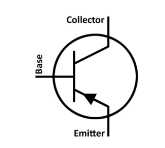
The arrow pointing outward from the base indicates the direction of conventional current flow. For a PNP transistor, current flows from the emitter to the base, and then out through the collector.

B represents the base terminal
C represents the collector terminal
E represents the emitter terminal
A PNP (Positive-Negative-Positive) transistor is one of the two main types of bipolar junction transistors (BJTs), the other being NPN (Negative-Positive-Negative). PNP transistors operate by controlling the current flowing between the collector and emitter terminals, with the base terminal controlling this current.
Here's a basic explanation of how a PNP transistor works:
Structure: A PNP transistor consists of three semiconductor regions: the emitter, the base, and the collector. These regions are doped differently to create two PN junctions. The emitter is heavily doped with P-type material (positive charge carriers), the base is lightly doped with N-type material (negative charge carriers), and the collector is moderately doped with P-type material.
Forward Biasing: When a positive voltage is applied to the base terminal relative to the emitter terminal, it forward biases the base-emitter junction. This means that the positive voltage repels the holes (positive charge carriers) in the P-type material of the base towards the N-type material of the emitter. Similarly, it attracts the electrons (negative charge carriers) in the N-type material towards the base. This action allows current to flow across the base-emitter junction.
Transistor Action: As current flows from the emitter to the base, it creates a larger current flow between the collector and the emitter terminals. This is because the base-emitter current controls the amount of current flowing between the collector and emitter. The collector current is typically much larger than the base current, amplifying the input signal.
Output Control: The amount of collector current is controlled by the base current. By varying the base current, the collector current can be proportionally adjusted, allowing the transistor to function as an amplifier or a switch.
Reverse Biasing: When a negative voltage is applied to the base relative to the emitter, it reverse biases the base-emitter junction, preventing current flow across it. This state turns off the transistor.
In summary, a PNP transistor works by using a small current at the base terminal to control a larger current flowing between the collector and emitter terminals. This allows it to amplify signals or act as a switch in electronic circuits.
In both amplifier and switch applications, the PNP transistor's ability to control a larger current with a smaller input current provides versatility and efficiency in electronic circuit design.
PNP transistors can be used as amplifiers in electronic circuits. By controlling a small current at the base terminal, the PNP transistor can allow a much larger current to flow between the collector and emitter terminals. This ability to amplify signals makes PNP transistors crucial components in audio amplifiers, radio frequency (RF) circuits, and various other electronic devices where signal amplification is required.
PNP transistors can also be used as switches in electronic circuits. When the base-emitter junction is forward biased (i.e., a small current is applied to the base terminal relative to the emitter terminal), the transistor is in its "on" state, allowing current to flow freely from the collector to the emitter. Conversely, when the base-emitter junction is reverse biased (i.e., no current or a negative voltage is applied to the base terminal relative to the emitter terminal), the transistor is in its "off" state, and it effectively blocks the flow of current between the collector and emitter.
This switching behavior is utilized in various applications, such as digital logic circuits, power control circuits, and voltage regulation circuits. PNP transistors are commonly employed in "high-side" switching configurations, where the load is placed between the collector and the positive power supply, allowing the transistor to switch the flow of current to the load on and off.
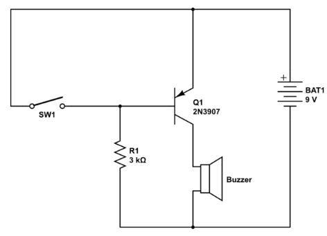
Here is an example of a PNP transistor circuit:

PNP transistor as a switch circuit
This circuit uses a PNP transistor to turn on and off an LED. When the switch is closed, the base of the transistor is connected to ground, which turns the transistor on and allows current to flow from the collector to the emitter, lighting the LED. When the switch is open, the base of the transistor is disconnected from ground, which turns the transistor off and prevents current from flowing through the LED.
Components:
PNP transistor (e.g., 2N3904)
LED
Resistor (e.g., 1kΩ)
Switch
Battery (e.g., 9V)
How it works:
When the switch is closed, the base of the transistor is connected to ground. This causes the transistor to turn on, and current flows from the collector to the emitter, lighting the LED.
The resistor limits the amount of current that flows through the LED, preventing it from being damaged.
When the switch is open, the base of the transistor is disconnected from ground. This causes the transistor to turn off, and no current flows through the LED.
This is just a simple example of how a PNP transistor can be used. PNP transistors can be used in a variety of circuits, including amplifiers, logic gates, and power supplies.
There isn't a single, universal code for PNP transistors like there is for resistors or capacitors. However, PNP transistors are identified using two main systems:
This is the most common system, used by manufacturers worldwide. The code consists of:
A leading digit:
1 for diodes
2 for bipolar transistors (including PNP)
3 for four-leaded devices, etc.
A letter:
Always "N" for JEDEC codes
A sequential number:
Typically between 100 and 9999
Optional suffix:
May indicate different versions or characteristics, e.g., 2N2222A has higher gain than 2N2222.
Examples of PNP transistor codes:
2N2222: General-purpose PNP transistor
2N4402: Another general-purpose PNP transistor
BC557: Low-noise PNP transistor
This system is less common but sometimes used by Japanese manufacturers. The code consists of:
A leading digit:
1 for diodes
2 for transistors
3 for thyristors, etc.
Two letters:
SA: PNP high-frequency transistor
SB: PNP audio-frequency transistor
SC: NPN high-frequency transistor
SD: NPN audio-frequency transistor
etc.
A sequential number:
Typically between 10 and 9999
Optional suffix:
Similar to JEDEC codes.
Examples of PNP transistor codes:
2SA1015: General-purpose PNP transistor
2SC1815: Another general-purpose PNP transistor
Important Note:
It's crucial to always consult the datasheet for the specific PNP transistor you're using. The datasheet provides detailed information about the transistor's characteristics, including its code, pinout, voltage/current ratings, and other crucial parameters for using it safely and effectively in your circuit.
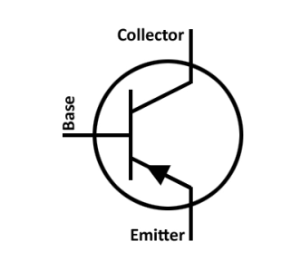
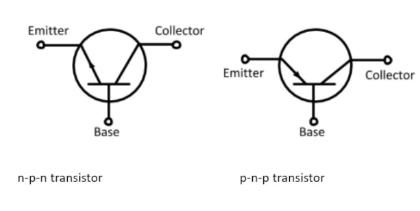
Both NPN and PNP transistors share a similar symbol structure with three terminals: collector (C), base (B), and emitter (E). However, the key difference lies in the arrowhead, which indicates the direction of conventional current flow:

Arrowhead points outward, signifying conventional current flow from the emitter to the base.
This implies a negative voltage on the base is needed for activation.
Arrowhead points inward, signifying conventional current flow from the base to the emitter.
This implies a positive voltage on the base is needed for activation.
In a circuit where a PNP transistor is used as a switch or an amplifier, the output terminal is often referred to as a "sourcing output" because the transistor sources current from the output to the load.
When the PNP transistor is in its active mode (turned on), current flows from the emitter terminal to the collector terminal. In this configuration, the collector terminal is typically connected to the positive supply voltage (Vcc), and the load is connected between the collector and the output terminal.
As a result, the output terminal of the PNP transistor effectively sources current to the load, hence the term "sourcing output." This means that the output terminal is providing current to the load, allowing the load to operate or be powered.
In conclusion, PNP transistors stand as crucial components in modern electronics, facilitating tasks ranging from signal amplification to circuit switching. With their ability to control substantial currents with minimal input, PNP transistors offer efficiency and versatility, making them indispensable in various electronic applications. Through understanding their symbol, operation principles, functions, and practical examples, engineers and enthusiasts alike can harness the capabilities of PNP transistors to design innovative and efficient electronic systems.
What is the difference between NPN and PNP transistors?
While both NPN and PNP transistors serve similar functions as amplifiers and switches, their operating principles, biasing requirements, and majority charge carriers differ, leading to distinct characteristics and applications in electronic circuits.
What are PNP transistors used for?
PNP transistors find widespread use in electronic circuits as both amplifiers and switches, offering versatility and efficiency in various applications. Whether it's boosting signal strength in an amplifier or controlling power flow in a switch, PNP transistors play a crucial role in modern electronics.
What is the most common PNP transistor?
The 2N3906 is the most commonly used general-purpose PNP transistors in electronics. It is widely available and is often recommended for use in various electronic projects, especially for through-hole PCB (Printed Circuit Board) and breadboard prototyping due to its ease of use.
Is 2N2222 a PNP?
No, the 2N2222 is not a PNP transistor; it is an NPN (Negative-Positive-Negative) transistor.
Which transistor PNP or NPN would you prefer to use as an amplifier?
Both NPN and PNP transistors can be used effectively as amplifiers, depending on the specific requirements of the circuit and the desired configuration. However, historically NPN transistors have been more commonly used in amplifier circuits due to some inherent advantages and their widespread availability.
In summary, while NPN transistors are often the default choice for amplifier circuits, PNP transistors can also be used effectively depending on the specific requirements of the circuit and the desired performance characteristics.
Can you use a PNP transistor as a switch?
Yes, PNP transistors can be used as switches in electronic circuits. When properly biased, a PNP transistor can function as an electronic switch that controls the flow of current between its collector and emitter terminals.