mars 31, 2021
2509
The directional coupler is used to sample a small amount of input signal power for measurement. Port 1 is the input port; Port 1 is the input port. Port 2 is the output port; Port 3 is the coupling port; Port 4 is the isolation/terminated port, usually terminated to 50Ω to minimize reflections.
However, when we measure the input power of a device under test (DUT), especially in an automated measurement system, we use a power sensor with a directional coupler. When measuring the 1dB compression point, by changing the input power and measuring the output power, we must measure and calculate the loss of the power sensor connected to port 3 and the input to the DUT to calculate the loss to correct the measured value. It is powered by the power sensor (Figure 1). In this article, this loss is expressed as the input loss Lpi of the power sensor.

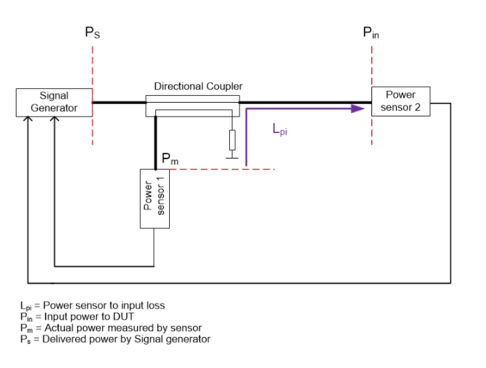
Figure 1 The automated measurement system uses a directional coupler and a power sensor.
The Lpi loss compensates for P in the power level measured by the power sensor. At first glance, the loss measurement method is shown in Figure 2, but this method of measuring loss has not been formulated correctly.
The power measured by the power sensor:
Pm=Pin–|Lpi|(1)

Figure 2 This is how the power sensor is used to measure power.
Calculate the sign agreement result of the power flowing into the element according to the settings shown in Figure 3.
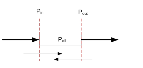
Figure 3 This is how power flows into the component.
The trend will be as follows:
Pout=Pin–Patt (2)
Pin=Pout+Patt (3)
Now, let us divide the path of Lpi loss into two parts, as shown in Figure 4.
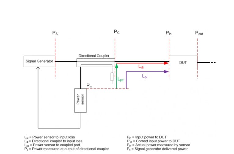
Figure 4 Lpi loss is the sum of two parts: Lpc and Ldi.
Power sensor input loss:
|Lpi|=|Lpc|+|Ldi|(4)
Now, moving from point Pm or sensor input to point Pin or DUT input, the Lpc loss should be added to the measured power level at Pm to reach the power level at point Pc. Finally, since Ldi is the cable loss, the Ldi loss should be subtracted from Pc to reach the power level at the Pin point. The actual input power of the DUT measured by the sensor:
P”in=Pm+|LPC|–|Ldi|(5)
Now, let us calculate the loss as shown in Figure 2.
Pin=Pm+|Lpi|=Pm+(|Lpc|+|Ldi|) (6)
This calculation seems logically correct, but as mentioned above, the Ldi loss should not be added to the total loss; instead, it should be subtracted from the total loss.
P"in=Pm+|LPC|–|Ldi|(7)
To find the errors in these methods, just use the following formulas.
Error=Pin-P”in=2×|L2|(8)
Here, the error of the measured power level calculated at Pin is 2×|Ldi|. Higher than the accurate power level.
Therefore, the following formula should be used to calculate the loss between the power sensor and the DUT input.
|Power sensor input loss|=|Lpc|–|Ldi|(9)
Finally, this is how to actually measure the loss.
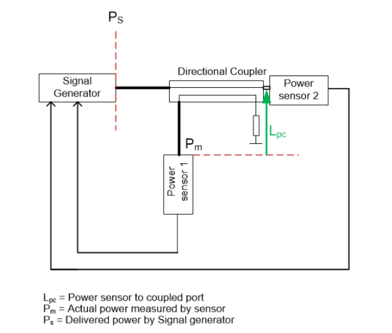
Figure 5 is a more practical way to measure loss.
Since the loss between the incident power and the received power of the directional coupler is negligible, in the first step, we use the power sensor connected to the output of the directional coupler to measure the output power, and subtract the difference between the two power sensors. Measure the power and find that Lpc fails.
In the second stage, we use a network analyzer to measure the loss caused by the cable between the directional coupler and the DUT input, the attenuator and the hybrid coupler (denoted by Ldi). Finally, we calculate the total loss according to Equation 9.
Siamack Ghadimi has a PhD in electrical engineering and is an assistant professor at the university.
