novembre 17, 2023
723
A comparator IC is a device used to compare two or more data items to determine whether they are equal, or to ascertain their size relationship and order of arrangement. A circuit or device capable of performing this comparison function is known as a comparator.

In essence, a comparator is a circuit that compares an analog voltage signal against a reference voltage. The two inputs of a comparator are analog signals, while its output is a binary signal, either 0 or 1. The output remains constant when the difference in input voltage increases or decreases, provided the sign of the voltage remains unchanged.
A comparator can be conceptualized as a 1-bit Analog-to-Digital Converter (ADC). An operational amplifier (op-amp) without negative feedback can theoretically serve as a comparator. However, due to the high open-loop gain of op-amps, they are only suitable for very small differential input voltages.
Additionally, op-amps typically have longer delay times, which may not meet practical requirements. Comparators, after adjustment, can offer minimal time delays, though their frequency response characteristics are somewhat limited. To prevent output oscillations, many comparators incorporate internal hysteresis circuits. The threshold of a comparator is fixed, with some having a single threshold, while others feature dual thresholds.
Hysteresis Voltage: This is the voltage difference between the two inputs of a comparator at which the output state changes when crossing zero. To prevent output oscillations due to small fluctuating voltages at the input, modern comparators often have a few millivolts of hysteresis voltage.

The presence of hysteresis voltage creates two switching points: one for detecting rising voltage and another for falling voltage. The difference between these voltage thresholds (VTRIP) equals the hysteresis voltage (VHYST). The offset voltage of a hysteresis comparator is the average of TRIP and VTRIP-.
Bias Current: Ideally, a comparator's input impedance should be infinite, meaning it would not affect the input signal. However, in practice, comparators do not achieve infinite input impedance. Bias current (Ibias) is defined as the median of the two comparator input currents and is used to measure the impact of input impedance. For instance, the MAX917 series comparators have a maximum bias current of just 2nA.
Beyond-the-Rail Swings: To optimize the operating voltage range of comparators, Maxim Integrated Products uses a structure where NPN and PNP transistors are paralleled at the input stage, allowing the input voltage of the comparator to extend beyond the power supply limits. This feature enables the comparator to operate with input voltages as low as the lowest level and 250mV above the supply voltage.
Drain-Source Voltage: Since comparators only have two distinct output states (zero level or supply voltage), and those with full supply swing capabilities use emitter followers in their output stages, the input and output signals have a minimal voltage difference. This difference depends on the saturation voltage of the internal transistors of the comparator, corresponding to the drain-source voltage in MOSFETs.
Output Delay Time: This includes the transmission delay caused by the passage of the signal through the components and the rise and fall times of the signal. For high-speed comparators like the MAX961, typical delay times can reach up to 4.5ns, with a rise time of 2.3ns. Various factors, including temperature, capacitive load, and input overdrive, can influence delay times.
Zero-Crossing Voltage Comparator: A typical amplitude comparison circuit, where the circuit diagram and transfer characteristic curve are as shown.
Voltage Comparator: By connecting one input of a zero-crossing comparator to a fixed voltage instead of ground, a voltage comparator is formed.
Window Comparator: This circuit consists of two amplitude comparators and some diodes and resistors. It saturates positively when the high-level signal voltage exceeds a certain value (VH) and negatively when the low-level signal voltage falls below a certain value (VL). This comparator has two thresholds, and its transfer characteristic curve resembles a window, hence the name.
Hysteresis Comparator: This involves drawing a resistive voltage divider from the output to the non-inverting input terminal. When the input voltage VI is less than the upper threshold VT, the comparator outputs a positive saturation voltage. When VI is greater than the lower threshold VT’, the comparator outputs a negative saturation voltage.
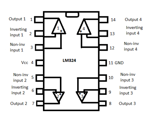
Common chips include LM324, LM358, uA741, TL081/2/3/4, OP07, OP27, all of which can be used as voltage comparators (without negative feedback). LM339 and LM393 are professional voltage comparators with fast switching speeds and short delay times, suitable for specialized voltage comparison applications. Essentially, they are also a type of operational amplifier.

The working principle of a comparator is straightforward. It has a positive and a negative leg. When the voltage at the positive leg is higher, the comparator's output "asserts" (or drives) a signal. With open-collector output, the output leg of the comparator is the collector of a transistor or the drain of an FET. With push-pull output, the comparator has a "totem pole" output, similar to that in an operational amplifier. Open-collector outputs are used when the load and the comparator use different power supplies.
This setup can drive a 12V solenoid, even though the comparator may only operate at 3.3V. Another purpose of open-collector output is to minimize static current when the output is off. In totem pole stages, no base current flows through the N-type output transistor, but some base current always flows through one of the two output transistors.
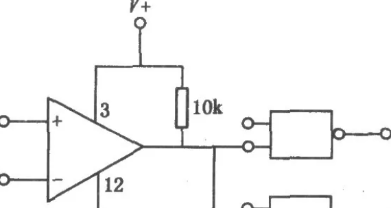
However, open-collector outputs have some drawbacks. For instance, they require external pull-up resistors. These resistors must complete the pull-up task during the high-resistance cycle so that when the output is below the off state, the comparator can switch more quickly, and the pull-up resistor makes the output high.
Therefore, open-collector outputs are not suitable for applications requiring symmetrical waveforms, such as clock recovery circuits. If your circuit does not require level shifting, you should choose push-pull outputs, such as the ALD2321APC, which can provide an output drive capability of 24mA and a quiescent current of 90µA.
High-speed comparators may also have a latched output, allowing the output to be held in a known state, meeting the setup and hold time requirements of subsequent digital inputs. Once the digital part reads the comparator's output, the latch pin can be released, allowing the output to track the input.
High-speed comparators may also use -5V to 0V ECL (Emitter Coupled Logic) levels. PECL (Positive Emitter Coupled Logic) outputs have the same voltage swing but operate from 0V to 5V. There are also RSPECL (Reduced Swing PECL) outputs. Some high-speed comparators have two output legs with LVDS (Low Voltage Differential Signaling) outputs, switching 300mV in a complementary manner around a 1.2V common-mode voltage. These outputs can be directly fed to the differential inputs of an ADC.