janvier 05, 2024
1566
A capacitor is a fundamental electronic component that plays a crucial role in various electronic circuits. Its ability to store and release electrical energy makes it essential in applications ranging from power supplies to signal processing. In electronic schematics, capacitors are represented by specific symbols that convey their characteristics. Let's delve into the diverse world of capacitor symbols and explore their meanings.
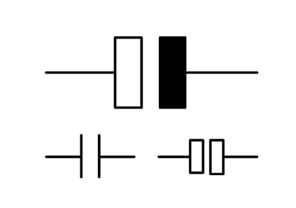
The symbol for a capacitor is a set of parallel lines, resembling plates separated by a gap. This generic symbol represents the basic construction of a capacitor and is widely used in electronic circuit diagrams to indicate the presence of a capacitor component. It is a visual shorthand that conveys the fundamental property of capacitors – the ability to store and release electrical energy.
Capacitance Symbol
Capacitance, a fundamental property of capacitors, is denoted by the symbol "C" in the world of electronics. It is used in equations, schematics, and circuit diagrams to represent the inherent ability of a capacitor to store charge. In mathematical terms, capacitance is the ratio of the stored electric charge to the potential difference across the capacitor's terminals.
Capacitance is a fundamental electrical property that characterizes the ability of a capacitor to store electrical charge when a voltage difference exists between its conductive plates. It is a crucial parameter in electronic circuits, influencing the behavior of capacitors in various applications such as energy storage, filtering, and signal coupling.
The symbol used to represent capacitance in electrical schematics and formulas is the uppercase letter C. The unit of capacitance is the farad (F), named after the pioneering physicist Michael Faraday. One farad is defined as one coulomb of charge stored per volt of potential difference across the capacitor.
In equations and circuit diagrams, the capacitance symbol (C) is employed to denote the magnitude of capacitance. For instance, in the formula Q = CV, where Q is the charge stored on the capacitor and V is the voltage across its terminals, C represents the capacitance. This fundamental relationship illustrates that the charge stored on a capacitor is directly proportional to its capacitance and the voltage applied across it.
Capacitance values can vary widely, and different capacitors are designed to have specific capacitance ratings based on their intended applications. Common subunits of the farad include microfarads (μF), nanofarads (nF), and picofarads (pF), which are used to express capacitance values over a broad range.
The unit of measurement for a capacitor's capacitance is the microfarad (μF). Represented by the symbol μ, microfarads indicate the amount of charge a capacitor can store. This symbol is essential for specifying capacitor values in electronic designs.
Capacitors, electronic components designed to store and release electrical energy, are commonly characterized by their capacitance, a measure of their ability to store charge. Capacitance is expressed in units of farads (F), with additional SI prefixes used to denote various orders of magnitude.
The microfarad (μF) is one such prefix used to represent a subunit of the farad. It is equal to one millionth of a farad, making it a convenient unit for specifying capacitance values in a practical range for electronic applications. The symbol for microfarads is denoted by the Greek letter mu (μ) followed by the capital letter F, forming the symbol μF.
In the realm of capacitor values, it is common to encounter capacitors with capacitance expressed in microfarads, nanofarads (nF), and picofarads (pF). Each of these prefixes signifies a different order of magnitude. Specifically, one microfarad is equivalent to 1,000 nanofarads or 1,000,000 picofarads. This hierarchical arrangement allows for a systematic representation of capacitance values, facilitating the selection of capacitors suitable for diverse electronic circuits and applications.
The list of SI prefixes for farads includes:
Microfarads (μF): 1 μF = 1 × 10^(-6) F
Nanofarads (nF): 1 nF = 1 × 10^(-9) F
Picofarads (pF): 1 pF = 1 × 10^(-12) F
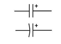
Electrolytic capacitors, including aluminum electrolytic and tantalum capacitors, known for their high capacitance values, are symbolized by a unique design. The symbol features an arrow, indicating the capacitor's polarity, crucial for correct circuit connections.
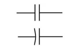
Non-electrolytic capacitors, such as ceramic and film capacitors, have symbols distinct from electrolytic ones. They lack the polarity arrow, emphasizing their non-polar nature. This is vital for avoiding circuit malfunctions.
Understanding the multitude of capacitor types is crucial for effective circuit design. Let's explore various types and their corresponding symbols.
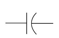
Fixed capacitors, with a constant capacitance value, share a common symbol. This symbol is straightforward, representing a capacitor with unchanging characteristics.
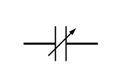
Variable capacitors, used for tuning applications, have a distinct symbol. It features an arrow, indicating its adjustable nature.
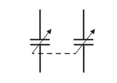
In cases where multiple capacitors are ganged or connected together, a unique symbol conveys this arrangement. It simplifies complex circuit layouts.
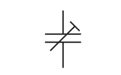
Trimmer capacitors, designed for fine-tuning, are represented by symbols reflecting their adjustable nature. These symbols often incorporate an arrow or a set of parallel lines.
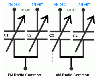
Capacitors used in tuning circuits, crucial for radio frequency applications, have symbols denoting their specific role. These symbols help engineers design effective tuning circuits.
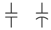
Non-polarized capacitors, such as ceramic and film capacitors, lack a specific polarity. The non-polarized capacitor symbol is a straightforward representation of the capacitor's ability to function regardless of its orientation in the circuit. The symbol is the standard capacitor icon, featuring two parallel lines representing the plates separated by a gap.
This symbol indicates that the capacitor can be connected in either direction within the circuit, simplifying circuit design and installation.
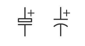
Polarized capacitors, like electrolytic and tantalum capacitors, have a specific orientation due to their internal construction. The polarized capacitor schematic symbol includes the standard capacitor icon with an additional marker denoting the positive terminal. This polarity is crucial for proper circuit functionality and prevents potential damage if connected incorrectly.
The polarity marker is often represented by a curved line or an arrow, indicating the direction of the positive terminal. Connecting a polarized capacitor in reverse can lead to electrolyte leakage or even capacitor failure.
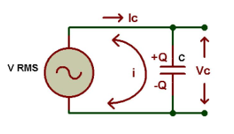
The symbol for an AC capacitor is typically a pair of parallel lines, representing the plates of the capacitor, with a curved line or squiggle connecting them. This curved line indicates that the capacitor is designed for use in AC circuits.
The symbol for a DC capacitor is similar, but it may lack the curved line or squiggle. It's essentially the two parallel lines representing the plates without the additional feature to signify AC.
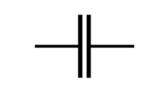
The symbol for a Mylar capacitor, like other capacitors, is a basic representation used in electronic circuit diagrams. The Mylar capacitor is a type of film capacitor, and its symbol typically looks like two parallel lines representing the plates of the capacitor with no polarity markings.
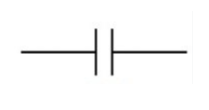
The symbol for a polyester capacitor, like other capacitors, is a basic representation used in electronic circuit diagrams. Polyester capacitors are a type of film capacitor, and their symbol typically looks like two parallel lines representing the plates of the capacitor with no polarity markings.
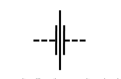
The symbol for a feedthrough capacitor, like other capacitors, is a basic representation used in electronic circuit diagrams. Feedthrough capacitors are often used to filter high-frequency noise and signals from one side of a shielded enclosure to another. The symbol for a feedthrough capacitor typically looks like a capacitor symbol with an additional line or arrow indicating the penetration through a barrier.
The symbol used to represent a capacitor in electronic circuit diagrams carries specific meaning and provides information about the capacitor's characteristics.
Parallel Lines:
The two parallel lines in the capacitor symbol represent the conductive plates of the capacitor. These plates store electrical charge when a voltage is applied across them.
Curved Line (or Squiggle):
The curved line or squiggle connecting the plates indicates that the capacitor is designed for use in AC (alternating current) circuits. It represents the alternating nature of the current in AC circuits.
Polarity (if applicable):
Some capacitor symbols may include polarity markings, indicating the orientation of the capacitor in the circuit. For polarized capacitors (such as electrolytic capacitors), one plate is positive, and the other is negative. The positive side is typically marked with a "+" sign.
No Curved Line (for DC Capacitors):
In the case of DC (direct current) capacitors or unpolarized capacitors, the symbol may lack the curved line. This signifies that the capacitor is intended for use in DC circuits.
In the capacitor symbol for electrolytic capacitors, the side with the longer line represents the positive (anode) side, and the side with the shorter line or no line represents the negative (cathode) side.
The positive side is typically marked with a "+" sign, indicating the anode. The absence of a specific marking on the other side implies that it is the cathode (negative side). This convention helps in correctly connecting capacitors in a circuit to ensure proper functionality.
It's important to note that not all capacitors are polarized, and for non-polarized capacitors, the symbol may not include markings for positive and negative sides.
Capacitor symbol and capacitance symbol are crucial concepts in electronic engineering. By understanding these symbols, engineers can accurately design and analyze circuits and ensure the correct use of capacitors in the circuit. The correct understanding and application of capacitors is crucial in today's electronic devices and systems, so knowledge of both subjects is fundamental and necessary for electronic engineers and technicians.
Read More: