novembre 23, 2020
2734
1; What is the return path?
The operation of electrical products requires a signal circuit to operate, as shown in the figure below (1), the negative electrode of the battery must also be connected to the blue wire before the light will turn on. In the early days, we can see that the telegraph system uses the "earth" as the ground plane of the signal loop, and another ground wire can be laid to reduce expensive costs. Or if a similar situation in modern life is when a light bulb is to be installed in the car, we can regard the "car shell" as the ground of the signal circuit, and connect the negative pole of the light bulb directly to the car shell and it will light up. One line is troublesome, and there is no need to consider the return path problem.
However, if you want to connect to various sensors or processors on the driving system, CAN (vehicle network system), or ADAS (advanced driver assistance system), it is not as simple as connecting directly and saving wires. It is easy to involve high-frequency/high-speed transmission, and it is necessary to pay attention to the integrity of its return path.

figure 1
same! For PCB design, if it is a low-frequency signal, the return path will return with the lowest impedance, but as the frequency increases, the current needs to return to the source in a closed loop, so the return path with the lowest inductance will be more considered, and it will usually correspond The return path on the upper and lower layers of the wiring is shown in the left picture (2) below, to avoid the problem of circuitous return paths caused by the inner layer cutting (2), so the return path of high-speed signals is more important.
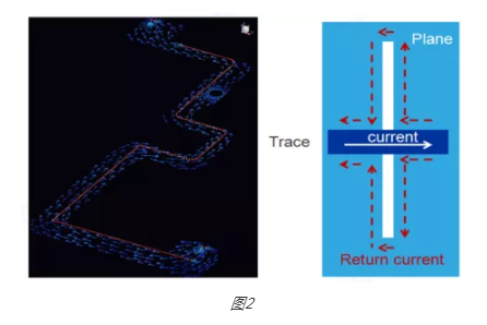
figure 2
2; What needs ReturnPath analysis?
As mentioned above, it is important to consider the return path of high-speed signals, because a little carelessness will greatly reduce the circuit function.
Generally speaking, because the DRC inspection of the standard PCB only checks whether the mouse wire is not connected and the safety distance is not enough, so the analysis such as ReturnPath is not easy to implement, and it often requires experienced veterans to open the relevant diagrams. The layers follow the adjacent layers of the high-speed signal wiring to ensure the return path and control the layout quality. Or set some rules on how to add STItchingVia to the Layout. The diagram of STItchingVia is shown in the following figure (3). As for the differential signal to hit Via, there are several STItchingVias next to it. That is another story!
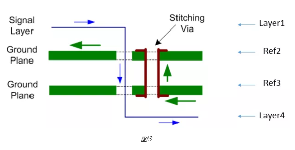
figure 3
Even in the end, it is necessary to add stitching capacitors to fill those moats that cannot be crossed (Moat), resulting in increased costs to improve the return path, as shown in the following figure (4) TI specification.
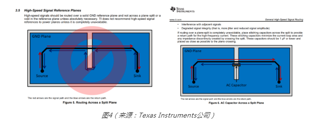
figure 4
So if we have an intuitive auxiliary analysis tool that will analyze the return path according to the geometry of the signal, and without Models, calculate the inductance ratio RPQF (ReturnPathQualityFactor, return path quality factor) as shown in Figure 5 below.
When the RPQF value is closer to 1, it means that the signal wiring is closer to the return path, and the higher it is, the more tortuous and farther the return path is.
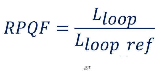
figure 5
Moreover, after the analysis is completed, the RPQF value of the relevant signal can be directly listed as shown in Figure 6 below, allowing us to quickly identify the severity of each signal and correct the undesirable part.
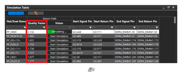
figure 6
Note: The other Impedance impedance analysis and coupling interference analysis in IDA (In-Design Analysis) are also the same. The quality control of various layouts can be quickly achieved by following the inspection process without Models. Fast screening analysis.
3; How to perform ReturnPath analysis?
Now Allegro has imported Sigrity's professional analog analysis technology, bringing IDA (In-Design Analysis, design synchronization analysis) into the PCB design process, helping PCB engineers to analyze in the design simultaneously, and find out common reflow path discontinuities in advance Problems can be solved in real time to quickly ensure the quality of the signal return path, which improves the design efficiency and reduces the probability of failure. It is also important that the ReturnPath check does not require Models and can be easily implemented with a simple process!