
How is the PWM timer used in motor control? How is the duty cycle microcontroller timer calculated?
Wilder Posté sur September 22, 2020
PWM duty cycle
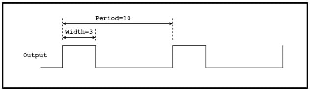
The duty cycle is the amount of time a digital signal is "active" relative to the signal period. The duty cycle is usually given as a percentage.
For example, a perfect square wave with equal high time and low time has a duty cycle of 50%. This is a graph showing the duty cycle in a general way.
Jenelle Posté sur September 22, 2020
Consider control resolution
There is one more thing to consider: Is the control resolution good enough?
The count in either direction from stop to full speed is 1,500. Therefore, the control resolution is a part of 1,500, which is less than 0.1%. For low-end servo motors, this is very high resolution, but for other types of motors, high resolution may be required.
Note how the first step above finds the smallest prescaler. The higher the frequency of entering the period counter, the higher the resolution.
Another way to solve this problem is to use more counts in the period counter to provide higher resolution.
Brigitte Posté sur September 22, 2020
Interrupt
Sometimes, strict control between PWM output and software is important. An effective way to synchronize the two is to use interrupts
When the period counter overflows and the width logic sees a match (the end of the output pulse), the PWM timer can usually choose to generate an interrupt request. If there are multiple channels, the interrupt service routine will usually read the registers in the timer to find out which channel requested the interrupt.